Built-in meshing functions
In this tutorial, we show how make simple meshes in CADDEE and how to visualize them. Currently, there is support for three kinds of meshes:
VLM mesh
1-D beam nodal mesh
Rotor mesh: extracting quantities such as the thrust origin/vecetor and making discretizations of the blade.
Important
In CADDEE, we distinguish between a meshes and a discretizations.
A discretization is a discrete representation of the geometric domain over which the numerical solution of a physics-based solver is defined
A mesh is a set of discretizations. (If the set only contains one disretization, the two are equivalent)
For example, in VLM analysis, a VLM mesh can consist of multiple discretizations of lifting (or non-lifting) surfaces, e.g., the wing and the tail. In CADDEE, each discretization is stored in a parent Mesh class object.
Important
CADDEE’s built-in meshing functions are intended to be helper functions that work reasonably well for relatively simple (wing) geometries. They are meant to automate the process of projecting points onto the outer mold line (OML). This allows changes to the geometry (e.g., during FFD) to be effectively propagated to physics-based solvers by re-evalutating meshes using the parametric coordinates and updated coefficients.
These helper functions work reasonably well for many (simple) geometries, e.g., for wings with no or moderate taper and relatively small curvature of the leading and trailing edge toward the wing. For more complicated geometries, they are not guaranteed to work.
We use an OpenVSP model of the Cessna C172 as the central geometry for this tutorial. First, we import the geometry and make a wing component for the main wing and the tail.
To plot the geometry, we use the Vedo package, which allows for interactive plots. These plots are NOT wrapped within the Jupyter Notebook cells. Screenshots of the geometry and meshes, however, can be saved and embedded using the matplotlib library.
import CADDEE_alpha as cd
import csdl_alpha as csdl
from vedo import settings
import matplotlib.pyplot as plt
import matplotlib.image as mpimg

settings.default_backend = "vtk"

# Start the CSDL recorder
recorder = csdl.Recorder(inline=True, expand_ops=True)
recorder.start()

# import C172 geometry
c172_geom = cd.import_geometry("c172.stp", rotate_to_body_fixed_frame=False)
c172_geom.plot()

# Make aircraft component and pass in the geometry
aircraft = cd.aircraft.components.Aircraft(geometry=c172_geom, compute_surface_area=False)

# Make wing geometry from aircraft component and instantiate wing component
wing_geometry = aircraft.create_subgeometry(search_names=["MainWing"])
wing = cd.aircraft.components.Wing(AR=7.72, S_ref=16.23, taper_ratio=0.73, geometry=wing_geometry)

# Make horizontal tail geometry component
h_tail_geometry = aircraft.create_subgeometry(search_names=["HTail"])
h_tail = cd.aircraft.components.Wing(AR=3.83, S_ref=4.04, taper_ratio=0.60, geometry=h_tail_geometry)
Importing OpenVSP file: /home/marius/Desktop/packages/lsdo_lab/CADDEE_alpha/CADDEE_alpha/utils/../../examples/test_geometries/c172.stp
VLM mesh
In this tutorial, the VLM mesh consists of a quad surface mesh/lattice of the wing and the tail. The main inputs to the make_vlm_surface helper function are
wing_comp (Wing): instance of a wing componentnum_spanwise (int): number of spanwise panelsnum_chorwise (int): number of chordwise panelsignore_camber (bool): if true, the lattice will track the camber line by projecting onto the top and bottom surface of the wing and taking the avergagespacing_spanwise (str): linear or cosine spacing of the panels in the spanwise directionchordwise_spanwise (str): linear or cosine spacing of the panels in the chordwise direction
Please refer to the API reference or the function doc-string for any additional function inputs.
vlm_mesh = cd.mesh.VLMMesh()
# make wing lattice
wing_chord_surface = cd.mesh.make_vlm_surface(
wing_comp=wing,
num_chordwise=3,
num_spanwise=26, # NOTE: must be even
ignore_camber=True, # Creates a flat lattice instead of tracking the camber line
spacing_spanwise="cosine", # bunch panels toward the wing tip
plot=False, # plot the projections
)
# make tail lattice
h_tail_chord_surface = cd.mesh.make_vlm_surface(
wing_comp=h_tail,
num_chordwise=1,
num_spanwise=10,
ignore_camber=True,
plot=True, # plot the projections
)
# Assign lattices to vlm mesh
vlm_mesh.discretizations["wing_vlm_lattice"] = wing_chord_surface
vlm_mesh.discretizations["h_tail_vlm_lattice"] = h_tail_chord_surface
# Extract the nodal coordinates
wing_chord_surface_nodal_coordinates = wing_chord_surface.nodal_coordinates.value
h_tail_chord_surface_nodal_coordinates = h_tail_chord_surface.nodal_coordinates.value
print("wing chord surface nocal coordinate\n", wing_chord_surface_nodal_coordinates)
print("h_tail chord surface nocal coordinate\n", h_tail_chord_surface_nodal_coordinates)
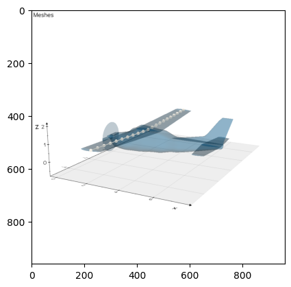
# Plot the VLM mesh
c172_geom.plot_meshes(
meshes=[wing_chord_surface_nodal_coordinates, h_tail_chord_surface_nodal_coordinates],
screenshot_file_name="vlm_mesh.png"
)
plt.imshow(mpimg.imread("vlm_mesh.png"))
Overwriting/updating mesh wing_8_vlm_camber_mesh
Overwriting/updating mesh wing_9_vlm_camber_mesh
wing chord surface nocal coordinate
 [[[ 2.98021    -5.59658863  1.06278079]
  [ 2.9835539  -5.55578387  1.06133416]
  [ 2.99358374 -5.43396193  1.0572752 ]
  [ 3.01011813 -5.23290126  1.05046846]
  [ 3.03292772 -4.95553309  1.04107839]
  [ 3.06167991 -4.60590215  1.02924191]
  [ 3.09595541 -4.18910674  1.01513165]
  [ 3.13525443 -3.71122473  0.99895334]
  [ 3.17900362 -3.17922628  0.98085277]
  [ 3.22656581 -2.60086442  0.96136301]
  [ 3.27724665 -1.98457768  0.94049913]
  [ 3.33030736 -1.33935133  0.91865552]
  [ 3.3849742  -0.6745942   0.89615072]
  [ 3.44045    -0.00001     0.87331288]
  [ 3.3849742   0.6745942   0.89615072]
  [ 3.33030736  1.33935133  0.91865552]
  [ 3.27724665  1.98457768  0.94049913]
  [ 3.22656581  2.60086442  0.96136301]
  [ 3.17900362  3.17922628  0.98085277]
  [ 3.13525443  3.71122473  0.99895334]
  [ 3.09595541  4.18910674  1.01513165]
  [ 3.06167991  4.60590215  1.02924191]
  [ 3.03292772  4.95553309  1.04107839]
  [ 3.01011813  5.23290126  1.05046846]
  [ 2.99358374  5.43396193  1.0572752 ]
  [ 2.9835539   5.55578387  1.06133416]
  [ 2.98021     5.59658863  1.06278079]]

 [[ 2.57380667 -5.59658863  1.06566625]
  [ 2.57603594 -5.55578387  1.06422685]
  [ 2.58272249 -5.43396193  1.06010284]
  [ 2.59374542 -5.23290126  1.05322462]
  [ 2.60895182 -4.95553309  1.04373594]
  [ 2.62811994 -4.60590215  1.03177516]
  [ 2.65097028 -4.18910674  1.01751671]
  [ 2.67716962 -3.71122473  1.0011685 ]
  [ 2.70633575 -3.17922628  0.98290884]
  [ 2.73804387 -2.60086442  0.9631834 ]
  [ 2.7718311  -1.98457768  0.94210041]
  [ 2.80720491 -1.33935133  0.92002741]
  [ 2.84364947 -0.6745942   0.89728626]
  [ 2.88063333 -0.00001     0.87420859]
  [ 2.84364947  0.6745942   0.89728626]
  [ 2.80720491  1.33935133  0.92002741]
  [ 2.7718311   1.98457768  0.94210041]
  [ 2.73804387  2.60086442  0.9631834 ]
  [ 2.70633575  3.17922628  0.98290884]
  [ 2.67716962  3.71122473  1.0011685 ]
  [ 2.65097028  4.18910674  1.01751671]
  [ 2.62811994  4.60590215  1.03177516]
  [ 2.60895182  4.95553309  1.04373594]
  [ 2.59374542  5.23290126  1.05322462]
  [ 2.58272249  5.43396193  1.06010284]
  [ 2.57603594  5.55578387  1.06422685]
  [ 2.57380667  5.59658863  1.06566625]]

 [[ 2.16740333 -5.59658863  1.06855172]
  [ 2.16851797 -5.55578387  1.06711954]
  [ 2.17186125 -5.43396193  1.06293049]
  [ 2.17737271 -5.23290126  1.05598078]
  [ 2.18497591 -4.95553309  1.04639348]
  [ 2.19455997 -4.60590215  1.0343084 ]
  [ 2.20598514 -4.18910674  1.01990177]
  [ 2.21908481 -3.71122473  1.00338366]
  [ 2.23366787 -3.17922628  0.9849649 ]
  [ 2.24952194 -2.60086442  0.96500379]
  [ 2.26641555 -1.98457768  0.9437017 ]
  [ 2.28410245 -1.33935133  0.92139929]
  [ 2.30232473 -0.6745942   0.8984218 ]
  [ 2.32081667 -0.00001     0.87510429]
  [ 2.30232473  0.6745942   0.8984218 ]
  [ 2.28410245  1.33935133  0.92139929]
  [ 2.26641555  1.98457768  0.9437017 ]
  [ 2.24952194  2.60086442  0.96500379]
  [ 2.23366787  3.17922628  0.9849649 ]
  [ 2.21908481  3.71122473  1.00338366]
  [ 2.20598514  4.18910674  1.01990177]
  [ 2.19455997  4.60590215  1.0343084 ]
  [ 2.18497591  4.95553309  1.04639348]
  [ 2.17737271  5.23290126  1.05598078]
  [ 2.17186125  5.43396193  1.06293049]
  [ 2.16851797  5.55578387  1.06711954]
  [ 2.16740333  5.59658863  1.06855172]]

 [[ 1.761      -5.59658863  1.07143718]
  [ 1.761      -5.55578387  1.07001222]
  [ 1.761      -5.43396193  1.06575813]
  [ 1.761      -5.23290126  1.05873694]
  [ 1.761      -4.95553309  1.04905103]
  [ 1.761      -4.60590215  1.03684165]
  [ 1.761      -4.18910674  1.02228683]
  [ 1.761      -3.71122473  1.00559882]
  [ 1.761      -3.17922628  0.98702097]
  [ 1.761      -2.60086442  0.96682419]
  [ 1.761      -1.98457768  0.94530298]
  [ 1.761      -1.33935133  0.92277118]
  [ 1.761      -0.6745942   0.89955735]
  [ 1.761      -0.00001     0.876     ]
  [ 1.761       0.6745942   0.89955735]
  [ 1.761       1.33935133  0.92277118]
  [ 1.761       1.98457768  0.94530298]
  [ 1.761       2.60086442  0.96682419]
  [ 1.761       3.17922628  0.98702097]
  [ 1.761       3.71122473  1.00559882]
  [ 1.761       4.18910674  1.02228683]
  [ 1.761       4.60590215  1.03684165]
  [ 1.761       4.95553309  1.04905103]
  [ 1.761       5.23290126  1.05873694]
  [ 1.761       5.43396193  1.06575813]
  [ 1.761       5.55578387  1.07001222]
  [ 1.761       5.59658863  1.07143718]]]
h_tail chord surface nocal coordinate
 [[[ 7.12016788 -2.          0.457     ]
  [ 7.16114784 -1.6         0.457     ]
  [ 7.20212781 -1.2         0.457     ]
  [ 7.24310777 -0.8         0.457     ]
  [ 7.28408774 -0.4         0.457     ]
  [ 7.32506771 -0.00001     0.457     ]
  [ 7.28408774  0.4         0.457     ]
  [ 7.24310777  0.8         0.457     ]
  [ 7.20212781  1.2         0.457     ]
  [ 7.16114784  1.6         0.457     ]
  [ 7.12016788  2.          0.457     ]]

 [[ 6.40384638 -2.          0.457     ]
  [ 6.34827711 -1.6         0.457     ]
  [ 6.29270783 -1.2         0.457     ]
  [ 6.23713855 -0.8         0.457     ]
  [ 6.18156928 -0.4         0.457     ]
  [ 6.126      -0.00001     0.457     ]
  [ 6.18156928  0.4         0.457     ]
  [ 6.23713855  0.8         0.457     ]
  [ 6.29270783  1.2         0.457     ]
  [ 6.34827711  1.6         0.457     ]
  [ 6.40384638  2.          0.457     ]]]
<matplotlib.image.AxesImage at 0x7f284a0a44f0>
1-D Nodal (Box) Beam Mesh
The second tpype of mesh CADDEE has automated capabilities for is a box beam mesh, intended for beam analysis with rectangular cross-sections (not considering stringers). The main inputs to the make_1d_box_beam helper function are
wing_comp (Wing): instance of a wing componentnum_beam_nodes (int): number of beam nodes (must be odd)norm_node_center (float): the normalized beam node center with respect to the leading edge (the beam height is computed at the node center)norm_beam_width (float): the normalized beam width
beam_mesh = cd.mesh.BeamMesh()
# Make box beam discretization
wing_box_beam = cd.mesh.make_1d_box_beam(
wing_comp=wing,
num_beam_nodes=21, # NOTE: must be odd such that one node is always at the wing root
norm_node_center=0.5,
)
# Assign the box beam to the beam mesh object
beam_mesh.discretizations["wing_box_beam"] = wing_box_beam
# Extract the nodal coordinates
wing_box_beam_nodal_coordinates = wing_box_beam.nodal_coordinates.value
print("wing box beam nodal coordinates (x, y, z)\n", wing_box_beam_nodal_coordinates)
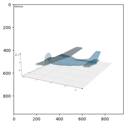
# Plot the mesh
c172_geom.plot_meshes(
meshes=[wing_box_beam_nodal_coordinates],
screenshot_file_name="beam_mesh.png"
)
plt.imshow(mpimg.imread("beam_mesh.png"))
Overwriting/updating mesh wing_2_1d_beam_mesh
Overwriting/updating mesh wing_box_beam
wing box beam nodal coordinates [[ 2.3705003  -5.59655377  1.07143593]
 [ 2.39350704 -5.03691174  1.05645777]
 [ 2.4165142  -4.47725266  1.04147759]
 [ 2.4395217  -3.91759351  1.02649586]
 [ 2.46252952 -3.35793438  1.01151275]
 [ 2.48553763 -2.79827526  0.99652837]
 [ 2.508546   -2.23861615  0.98154285]
 [ 2.53155462 -1.67895705  0.96655629]
 [ 2.55456345 -1.11929796  0.95156877]
 [ 2.57757248 -0.55963886  0.93658039]
 [ 2.60058171 -0.00001577  0.92159253]
 [ 2.57757248  0.55963886  0.93658039]
 [ 2.55456345  1.11929796  0.95156877]
 [ 2.53155462  1.67895705  0.96655629]
 [ 2.508546    2.23861615  0.98154285]
 [ 2.48553763  2.79827526  0.99652837]
 [ 2.46252952  3.35793438  1.01151275]
 [ 2.4395217   3.91759351  1.02649586]
 [ 2.4165142   4.47725266  1.04147759]
 [ 2.39350704  5.03691174  1.05645777]
 [ 2.3705003   5.59655377  1.07143593]]
<matplotlib.image.AxesImage at 0x7f369cb72970>